There currently aren’t any automated tests, so I can only speak to configurations I personally use:
Operating System: Known to work on both Windows and Linux. macOS is likely also fine, but untested.
Node.js: Currently works under Node 12, 14, and 16. Newer versions might work; older versions definitely don’t. This is mostly based on Node SerialPort’s support matrix, which is based on Node’s support matrix. If you need to run a separate copy of Node for this project, I recommend looking into nvm.
Serial Bridge’s configuration is stored in the file config.js. A sample configuration file is at config.example, so you can make a copy of this file and fill it in. The sample configuration file is full of comments, but it’s still a bit terse, so this section gets into all the gory details.
The only thing the configuration file is required to do is declare a config variable. This can either be an object, or a function that returns an object. That is:
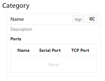
Serial ports are grouped by device, on the theory that devices plugged into the host will have more than one port each. Each device appears as its own element in the web UI home page, as depicted below, and each device also has a dedicated webpage showing the output of all ports on that device.
How a device is rendered on the web view homepage.
The devices key is the only mandatory configuration key. It is an array containing objects with the following keys:
Tip
If you are adding a number of similar devices (e.g. they all have the same nodes and just vary in port assignments), it can be convenient to make a function that takes the differing information as arguments and returns the complete device object. Then your configuration can do:
This is an object containing arbitrary extra data about a device. It is included in API requests that expose device information, but otherwise not used by Serial Bridge.
An array of nodes, Serial Bridge parlance for ports. Each node bidirectionally connects one serial port to a TCP port, and appears in the web UI as a terminal window:
A device’s web view, with three nodes connected to serial ports.
Each object in the nodes array contains the following keys:
The port’s bit speed as an integer. Any speed supported by the underlying operating system is allowed, but this must match the speed the connected device is using or you’ll end up receiving malformed data.
An array listing the buttons that should appear in the device web view. These buttons are located in the node’s titlebar, on the right side (but to the left of the layout buttons):
This is an object containing arbitrary extra data about a node. It is included in API requests that expose node information, but otherwise not used by Serial Bridge.
If Jenkins is integrated with Serial Bridge, this is the name of the lockable resource in Jenkins that corresponds to this device. When the device is reserved by a person or locked by a build, it will be shown in the web interface.
Most of this documentation assumes you will be using the web interface, but it’s actually optional. If this key is omitted, Serial Bridge won’t do anything but bridge serial ports to TCP ports. If this key is included, the object contains the following keys:
port – HTTP port to listen on. Defaults to 80.
ssl – SSL configuration. Including this will let the specified port speak both HTTP and HTTPS. The object contains the following keys:
cert – The SSL certificate.
key – The associated SSL private key.
passphrase – The encryption passphrase for the private key. If omitted, the key must be unencrypted.
The web view will show users connected to a device, both via the web UI and directly to node TCP ports. By default users are just identified as their hostname, but this can be enhanced via this configuration object containing the following keys:
identify – A function that attempts to identify a user given their hostname. See the users section for more details.
avatarSupport – A flag indicating if the identify function will also specify user avatars. This affects the help text the user is shown on the home page. Defaults to false.
name – The name of the remote. Shown on the home page in the corner of the device box.
url – The base URL of the remote, including the port if non-standard.
deviceRewriter – A function that takes an object describing the remote device and returns a modified copy of the device. This is intended to tweak the category and tags of the remote devices, but any fields can be changed.
An array of objects defining commands that can be executed in the device web view. These commands are shown in a dropdown menu. Each object contains the following keys:
label – The label to display in the menu item.
icon – The icon to display next to the menu item label. Icons are pulled from FontAwesome and are specified by the icon’s full class. For example, this icon is 'fasfa-smile'.
filter – A function that will be passed a (possibly undefined) device JSON object like the one returned by the devices API, and returns a boolean indicating if the function should be made available when the user is interacting with that device.
fn – The function to execute when the user clicks this command.
submenu – An array of commands/submenus to display beneath this menu item. The objects in this array contain the same keys listed here.
Every command object must contain exactly one of fn, if the menu item is a command, or submenu, if the menu item is a submenu.
An array of objects defining layouts that can be applied to the device web view. Each object contains the following keys:
name – A human-friendly name used to identify the layout.
devices – A filter to control which devices the layout can be used on. This can either be an array of device name strings, or a function that takes a device’s JSON representation and returns a boolean. By default, a layout is allowed on a particular device as long as the device contains all of the nodes referenced in the layout.
type – The type of the root layout cell. See the next section on layout structure for more information.
children – The children of the root layout cell. See the next section on layout structure for more information.
Each layout is comprised of cells that are organized into rows, columns, stacks, and nodes (a cell containing the actual node terminal). Structural (non-node) cells are described by objects containing the following keys:
type – 'row', 'column', or 'stack'.
height – The height of the cell. See the explanation of fractional units below.
width – The width of the cell. See the explanation of fractional units below.
children – An array of the cells nested within this one. Rows and columns can contain any cells and nest indefinitely, while stacks can only contain nodes. This can also be '*' to include all the nodes not specified elsewhere in the layout.
Node cells are the leaves of the layout, specifying the actual node that should be displayed at that location in the layout. Node cells are described by objects containing the following keys:
type – 'node'.
name – The name of the node to display here.
height – The height of the cell. See the explanation of fractional units below.
width – The width of the cell. See the explanation of fractional units below.
optional – True to skip this node if the device rendering the layout doesn’t have it. False (the default) if this layout should be unavailable to devices lacking this node.
The width and height fields in cell configuration are measured in fractional units. This means each value represents a fraction of the total width/height available, determined by dividing the value by the sum of all the values in that row/column. For example, if three cells in the same row specify widths 1, 2, and 3, they will be allocated 1/6th, 2/6th, and 3/6th of the row width, respectively. Any cell that does not specify a width or height will default to 1.
Configuration for the port-finding tool. Contains the following keys:
enabled – A flag indicating if the port-finding tool should be enabled. Giving users access to every serial port on the system has security implications, so this is false by default.
patterns – Pre-defined pattern sets, used to automatically identify nodes based on their output. Each key in this object is the name of the predefined set, while the value is an array of objects containing the following keys:
pattern – A string containing a regular expression to watch for.
name – The name of the node this pattern identifies.
A flag indicating if the configuration file should be reloadable. This will apply any changes made to devices since the server was loaded. A reload can be trigger by sending the server a SIGUSR2 signal, or via “Manage” -> “Reload configuration” from the web interface.
How to handle the files stored on the server when a user shares their terminal state. Contains the following keys:
dir – Directory to store saved state files in. Defaults to ./saved-state. Will be interpreted relative to the root Serial Bridge directory.
expireAfter – Minutes to retain a saved state file before deleting it. Defaults to 43200 (30 days). Can be set to undefined to never delete saved states.
maxSize – Maximum number of bytes a single saved state file can be. Defaults to undefined (no limit).
An array of hostnames and IP addresses to block from connecting to the web interface and node telnet ports. Serial Bridge will attempt to convert hostnames to IPs and the reverse on startup, but after that the blacklist is fixed. Best practice is to list exactly the string you see in the console output when the target host tries to connect.
The Serial Bridge web UI lists all the users connected to ports on a device, both on the home page and device page. For the latter case, users are pictured along the right side of the menu bar. Mousing over an avatar will show the user’s name, hostname, and a list of open ports:
I should stress here that Serial Bridge has no concept of accounts or logins. User information comes from two sources:
Provided by the user in the “Setup” section of the home page.
The users.identify function is an optionally asynchronous function that takes an object describing the user. This object has the following keys:
host – The user’s hostname.
displayName – The user’s real name.
email – The user’s e-mail address.
avatar – A URL for the user’s avatar image.
This object will only have some keys going into the users.identify function:
Key
Incoming
Outgoing
host
Yes
No
displayName
Maybe
Yes
email
Maybe
Yes
avatar
No
Yes
Keys marked “incoming” will (or may) be set on the object when users.identify is called. Keys marked “outgoing” can be updated by users.identify, although none are required. If unset, the user’s display name becomes their hostname and their avatar is left generic. If displayName and email are set going into the function, it’s because the user manually provided them, so the function should probably not modify them.
How to actually implement users.identify is left to you, based on the hostname conventions of your network. Sample code is provided in the example configuration file to extract a username from the hostname, look up the user’s name and e-mail in Active Directory, and then use Gravatar for the avatar.
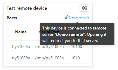
Serial Bridge can only connect to serial ports on the machine it’s running on. In other words, if you have devices plugged into multiple host machines, you will need to run Serial Bridge on each of them. However, you can list other Serial Bridge instances in the remotes configuration key to display their devices on your home page. These device listings are live, but clicking one will redirect you to the remote web UI.
Remote devices are identified on the right edge of the device box:
There’s also a per-user toggle on the top-right of the home page to disable showing remotes.
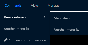
Commands are blocks of code from the configuration file that users can trigger on demand. Commands are accessed from the “Commands” menu on a device’s web page:
Any real command menu item (i.e. a menu item that isn’t just a submenu) must provide a fn function in the configuration file that is executed when the user clicks the menu item. This is an optionally asynchronous function taking one object containing functions to interact with the device. This object is typically named api; for example:
config={...commands:[{label:"Send 'hi' to 'test' node",icon:'fas fa-smile',asyncfn(api){api.sendln('test','hi');},}],...};
The api object contains the following functions:
getDevice()
Returns an object containing information about the current device. This object is the same one returned by the Devices API, so you can open that in a browser for more information.
send(nodeName:string,message:Buffer|string)
Sends the specified data to the specified node.
sendln(nodeName:string,message:string)
Send the specified data to the specified node, and append '\r\n'.
Pass incoming data from the specified node to the handler. If bufferLines is true, one complete line at a time is passed to the handler. Returns a function that can be called to stop receiving data.
drawTermLine(label:string,caps?:'start'|'end')
Draw a colored line in every terminal to delineate an event. caps indicates how the end of the line should look:
Show a modal dialog on the web interface. This interface is likely to change, but for the moment it displays a two-column table of information. For example, this call:
Layouts are saved arrangements of nodes on the device view. Layouts can be defined in the configuration file, and each user can also save custom layouts in their local storage. The current layout on the device view can be changed via the View ‣ Layout menu. Users can also preview layouts and choose which layout they want the device view to default to via the home view “Setup” tab:
Serial Bridge has some half-baked integration with Jenkins CI servers. Someday I might write a Jenkins plugin, but at the moment this requires some work on your part.
Serial Bridge can show the currently running build using the given device. It can also show a subdivision of the build, called a stage, and a subdivision of the stage, called a task. This information is shown on the home page and the device page’s titlebar:
This information is sent to Serial Bridge via an HTTP PATCH request. The API URL is <serialbridgehost>/api/jenkins/<lockname>, where <lockname> is the jenkinsLock value in the device’s configuration object. The following data should be sent in the PATCH request:
Operation
Data
Start build
startBuild: true
name: Build name
link: Build link
End build
result: true on success, false on failure
Start stage
pushStage: Stage name
End stage
popStage: true
Start task
pushTask: Task name
End task
popTask: true
Builds contain stages and stages contain tasks, so e.g. ending the current stage will also end the current task, if any.
This example cURL command starts a build on the device with lock name device1:
If you use the Jenkins Lockable Resources plugin to indicate who is currently using a device, you can reflect this information in Serial Bridge. Locks are shown in the same place as Jenkins builds:
Serial Bridge needs to know every time a Jenkins lock changes. This begs to be solved with a plugin, but lacking that, I currently solve it with incron and a Bash script. Incron is like cron, but events are triggered by filesystem events instead of time events. Every time Jenkins locks change, the file $JENKINS_HOME/org.jenkins.plugins.lockableresources.LockableResourcesManager.xml is updated. Incron can watch for this, and send the entire file to Serial Bridge, which will parse it and update its lock information.
Run incrontab-e to edit your incrontab file. Add an entry that triggers when a file is moved to the Jenkins home directory (Jenkins doesn’t write directly to the target XML file, it writes a new file and then renames it):
Then implement the specified file-moved.sh script. Incron will call it with the target directory name and filename, so it needs to check that the file is the one containing lock information and then POST it to Serial Bridge:
#!/bin/bashset-e
dir=${1:?Missing directory}file=${2:?Missing filename}if["$file"="org.jenkins.plugins.lockableresources.LockableResourcesManager.xml"];thencurl-XPOST-d@"$dir/$file"http://serial-bridge-host/api/lock
fi
Serial Bridge will respond with a full device object like one that would be returned by querying /api/devices/<id>. Each node within this object will include a TCP port, and connecting to a node’s TCP port will provide the other side of that node’s pipe.
If all node TCP connections are closed, the device is automatically removed (there is a 10 second grace period after first creating the device to give time for at least one connection to be established).
Depending on the node’s configuration, you will see some of these buttons in the node’s titlebar on the device’s web page:
The right three buttons control the page layout and are irrelevant here, but the left three are called “web links”. They correspond to the following:
telnet – Open the node’s TCP port in the system’s default telnet client.
raw – Open the node’s TCP port in PuTTY’s “raw” mode.
ssh – Connect to the node over SSH.
Browsers support telnet links natively and so the telnet web link will work with whatever your default Telnet client is. The other two options require you to install a supported client to handle those links, and possibly do some extra configuration to make the links work. Instructions on how to do this are on the Serial Bridge home page in the “Setup” tab. Raw and SSH links will not be shown to users who haven’t specified their preferred client on the “Setup” tab.
In addition to handling web links directly, the MobaXterm client supports displaying a list of connections from a remote source, which it calls “shared sessions”. Serial Bridge exposes a list of available connections in a format MobaXterm can read. This requires the paid “Professional Edition” of MobaXterm.
To add shared sessions to MobaXterm:
Go to “Settings” -> “Manage shared sessions”.
Click “Add”.
Choose the root node’s name and icon.
Set the backend protocol to “http / https”.
Set the sessions file URL to “<serialbridgehost>/mobaxterm.mxtsessions”.
Click “Save”, then “Apply”.
This URL takes some optional query parameters, e.g. <serialbridgehost>/mobaxterm.mxtsessions?key=c:\key.ppk. The parameters are:
host – The server’s hostname. This can usually be determined automatically, but if you get an “Unable to determine host” error this should be set to Serial Bridge’s own hostname.
key – A path to the private key to use for all SSH connections. If this parameter is provided but left blank, it defaults to <MyDocuments>\serial-bridge.ppk. If this parameter is omitted, no private key is used and you must provide a password when connecting.
The port-finding tool is accessible from the home page main menu, at Ports ‣ Find Ports. It is disabled by default to avoid exposing every serial port on the system to your entire network; see the portsFind configuration key to enable it.
Once enabled, the tool acts like a wizard and steps you through identifying the new ports. This is most useful when you are plugging in a number of ports at once. At a high level, the steps are:
Plug in the device and note which new ports appear.
Turn on the device and watch the output on the new ports to identify them.